ALLPLAN BRIDGE 2020

“World Innovation: Modeling, Analysis and Detailing in a single BIM solution for Bridges.”

ALLPLAN BRIDGE 2020 ÖZELLİKLERİ

Model creation without compromise

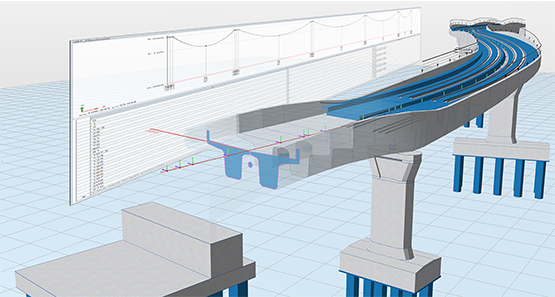
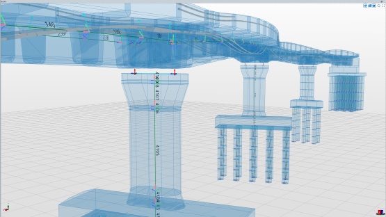
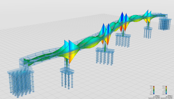
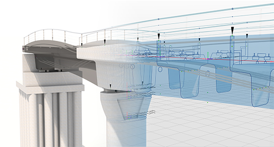
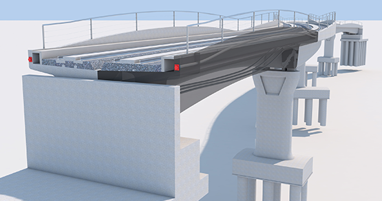
Allplan Bridge has been developed by recognized bridge experts – Allplan Infrastructure from Graz – and to the requirements of bridge engineers. The 3D parametric model description considers the road layout, bridge alignment and required cross-sections, making model configuration quick and efficient. Complex geometries including double curved alignment and variable cross-sections can be created easily with the help of alphanumeric entries and formulas. For example, the user only needs to define one typical cross-section and Allplan Bridge will accurately calculate all cross-section variants in accordance with the defined table(s) or/and formula(s). A complete 3D Bridge model cannot be generated more easily or quickly.


DefInIng A Cross-SectIon

You can define any cross-section and determine the geometry with its dependencies and variables. These parametric cross-sections can be adapted at any time and can be saved as a template and reused.

Modeling of composite and steel bridges

When defining the cross-section, standardized and repetitive profiles such as longitudinal stiffeners for steel and composite cross-sections can be easily positioned parametrically. The profile is first defined parametrically in a separate section or imported from the user library. The position and number of elements are then defined and automatically placed along a cross-section edge. The connection between the profile and the cross-section edge is also automatically adapted.

 
Prestressing made simple

Allplan Bridge makes it easy to model a wide range of types of pre-stressing: with immediate or later bond, internal and external, longitudinal, transverse and vertical, as well as with non-standard geometry. Based on user-defined 3D points, the program automatically generates the geometry of a tendon along the bridge structure. Each 3D Tendon point is specified by the position along the axis, and the position in the cross-section in relation to a reference point. In addition, direction angle and curvature radius of the tendon can be specified in each point. Selective parameters can be defined as variable. When calculating the detailed tendon geometry, the program determines these values automatically, using an intelligent algorithm minimizing the friction losses in the stressing process. A special point grid is available in the cross-section to ease the specification of the tendon position in the cross-section plane. This point grid facilitates copying and mirroring of the tendon in longitudinal and transverse direction.

Planning stressing sequences in Allplan Bridge

A stressing sequence can be defined for each tendon specified in the model. Stressing, wedge slip, and releasing are available actions. These actions are carried out at the begin of the tendon, at the end, or at both sides simultaneously. To optimize the management of tendon stressing, the sequences of stressing actions are stored as named “stress groups”. The tendons are assigned to the corresponding group via Drag&Drop, and automatically stressed in accordance with the group definition. In addition, the values can be adjusted individually for each tendon.

 
Changes made in no time at all

Allplan Bridge helps you to manage the inevitable changes that occur during the design process. The parametric model description is an ideal base for adapting design changes. The modifications are incorporated only at their origin and all other linked members are automatically updated. For example, if the road axis changes the complete bridge geometry will be adjusted. If only a certain structural member is modified only directly linked elements will be recalculated.


Automatic Derivation Of The Analysis Model

Thanks to breakthrough technology, Allplan Bridge automatically generates the analysis model from the geometrical model. This greatly reduces the amount of work and the susceptibility to errors. Hereby the engineer retains full control by specifying structural parts and those ones which contribute as load only. One additional analysis-relevant definition is the choice of generating a beam or a grillage model.

Assembling Construction Sequence Calculation

Allplan Bridge analyses the defined construction schedule and sets up all necessary calculation definitions in an automated process, like load cases, element activations and calculation actions. This includes input data for calculating nonlinear time effects, like creep and shrinkage. Complete transparency is granted, the user keeps full control of the generated items and an overview of the results at any time of construction.

 
Apply Additional Loads

The weight and the position of superimposed dead loads (like sidewalk, road pavement, etc.) are automatically retrieved from the geometrical model. The user needs to specify the point in time of the equipment installation, and consequently the load is applied on the structural system. Additional loads, like temperature change or wind loads, can be defined and applied easily as well.


Superposition

The user-friendliness of the superposition in Allplan Bridge is groundbreaking. The schematic definition of the superposition combines maximum flexibility with optimal overview. It is possible to select several stress components in userdefined stress points and perform a stress leading superposition. Furthermore, the superposition allows for storing corresponding results for selected elements.

 
Calculation of cross-section values

The calculation of cross-sectional values is an essential step in the generation of an analysis model. All cross-section values as well as the shear forces for the defined cross-sections are calculated automatically as soon as the corresponding calculation option is activated. The calculation supports all types of sections with an arbitrary geometry including monolithic and composite cross-sections, open and closed cross-sections, sections with one or more openings as well as thin-walled cross-sections. The stiffness matrix of the individual beam elements is automatically created considering the calculated cross-section values, beam geometry and material properties.

Performing Structural Analysis

A global static analysis based on the Bernoulli beam theory is performed for all automatically and manually generated calculation actions defined previously in the construction sequence definition. The analysis is enhanced to accurately consider the cross-section variation. Furthermore, the nonlinear calculation of time dependent effects is performed, considering design code formulas.

 
Save time with parametric object placement

Objects from the Allplan Engineering library can be referenced in Allplan Bridge to add further details such as lamp posts or anchor devices of tendons to the bridge model. To do this, reference points are defined in Allplan Bridge, using variables along the bridge. These points are linked to the object in the Allplan library using the respective name. When the parametric model is transferred to Allplan Engineering, the corresponding objects are positioned at these reference points. The position of these objects is automatically adjusted whenever the model is updated.

Smooth data exchange

Integrating road data used for road/bridge alignment is easily achieved via ALLPLAN’s open BIM platform Allplan Bimplus. The bridge engineer must only take over the road data and can immediately start with the bridge design. To assist the engineer even further, the bridge model can easily be transferred to analysis software for structural calculations. Once the design is completed, the parametric model can be transferred in Allplan Engineering for completion of pre-stressing and reinforcement drawings.

 
Convenient operation

Compared to mechanical engineering CAD software or traditional 2D drafting, working with Allplan Bridge is very convenient and specifically tailored to the requirements of bridge engineering. This leads to an essential optimization of the working speed. Furthermore, you can use Allplan Bridge on multiple monitors at the same time. Allplan Bridge automatically adapts its user interface to the screen size and resolution and is ideal for the use in powerful high-resolution monitors (4D/UHD with 3840×2160 pixels and more).


Intelligent database

Allplan Bridge benefits from a built-in database that is continuously logging modifications as the project progresses. This will benefit projects that have a long design period by ensuring project data is securely available for the duration of the project.

 
Technical support from bridge experts

ALLPLAN’s bridge design experts have over 30 years’ experience supporting engineers worldwide. ALLPLAN’s clients can benefit from our technical experts providing comprehensive consultancy, training and support.

ALUPLAN PROGRAM SİSTEMLERİ

Son 5 yıldaki tüm geliştirmelere göz atın

Allplan 2015-2020 – Allplan Architecture tüm yenilikler bir arada.

NEW FEATURES 2016-2020

 
ALLPLAN 2020
error: Content is protected !!