
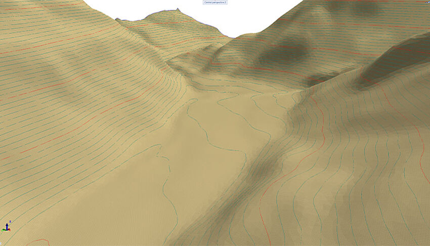
Terrain data can be imported in the form of large point clouds (e.g. from Scalypso) and displayed graphically. This makes it possible to use high-resolution terrain models as the basis for mass determinations within infrastructure projects.
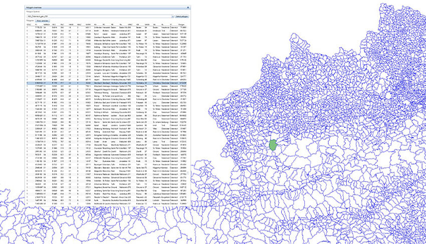
Geospatial data processing makes it possible to record property boundaries, floodplains, road networks, and more. This information can be used to identify critical zones or conflict points at an early stage and to take them into account during project planning. The imported geo-information can also be considered when creating output plans.
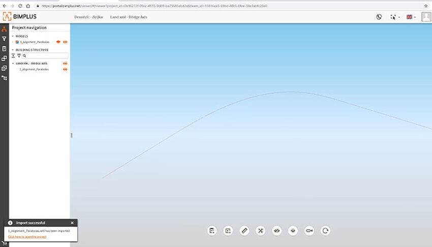
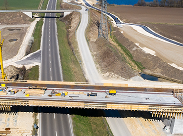
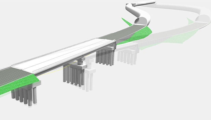
The import of data from road planning can be used as the basis for the axis definition of the bridge, and is carried out in Allplan Bridge via the open BIM platform Bimplus. The bridge engineer only has to import the data and can do everything from model creation, prestressing, structural analysis and detailing to plan creation with one solution.
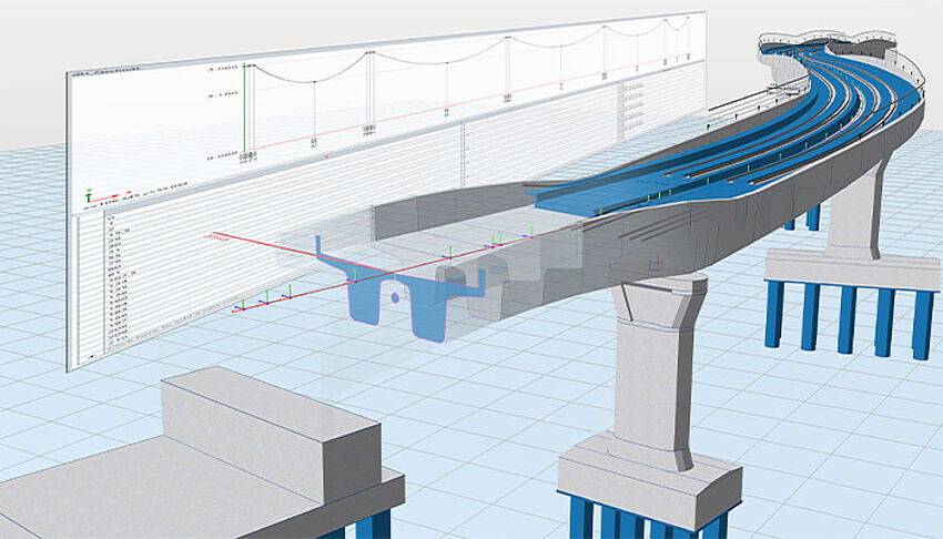
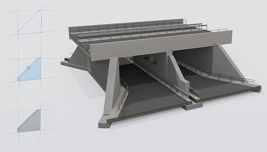
The modeling technique is tailored for bridges, especially for bridges with geometry directly governed by the axis. Once the axis is imported or defined, the user defines typical cross-section(s) which are extruded along the axis. The digital model generated in Allplan Bridge is completely parametric. Model changes can be made at any time and the dependent objects are automatically adjusted. Allplan Bridge is suitable for all phases of work – from the concept to the detailed design.
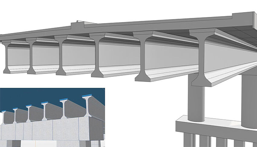
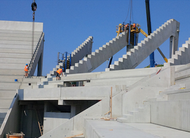
Precast girder bridges have one thing in common – their component geometry. The straight profile of precast girders is why their geometry is not directly impacted by the road or bridge axis. That is why Allplan Bridge provides special features and a specialized workflow. The reuse of girder shapes and lengths is a further typical feature of precast girder bridges and in Allplan Bridge “modular modeling” addresses this whilst providing an efficient workflow.
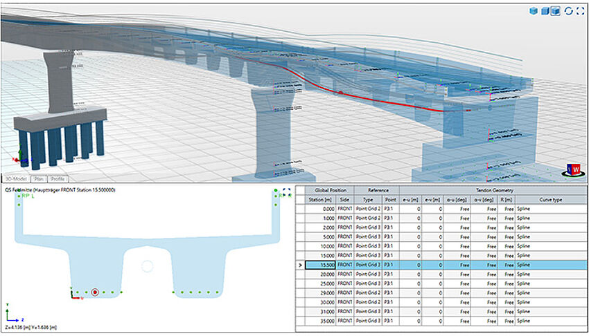
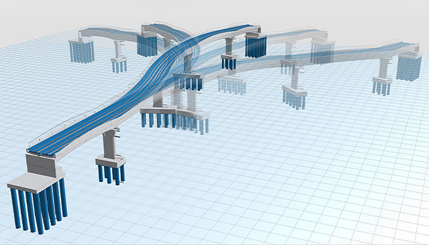
Allplan Bridge makes it easy to model a wide range of types of pre-stressing: with immediate or later bond, internal and external, longitudinal, transverse and vertical, as well as with non-standard geometry. Based on user-defined 3D points, the program automatically generates and optimizes the geometry of a tendon along the bridge structure.
The third modelling technique available in Allplan Bridge allows the user to parametrically model the entire bridge or its sub elements freely in 3D space using volumetric primitives and Boolean operations. In the first release of this new technology for volumetric primitives, advanced prisms are implemented – the basic shape of a prism is defined using the well-known cross-section definition. Because this is rather a more general parametric modeling technique, it can be used for parametric modeling of other infrastructure requirements as well.
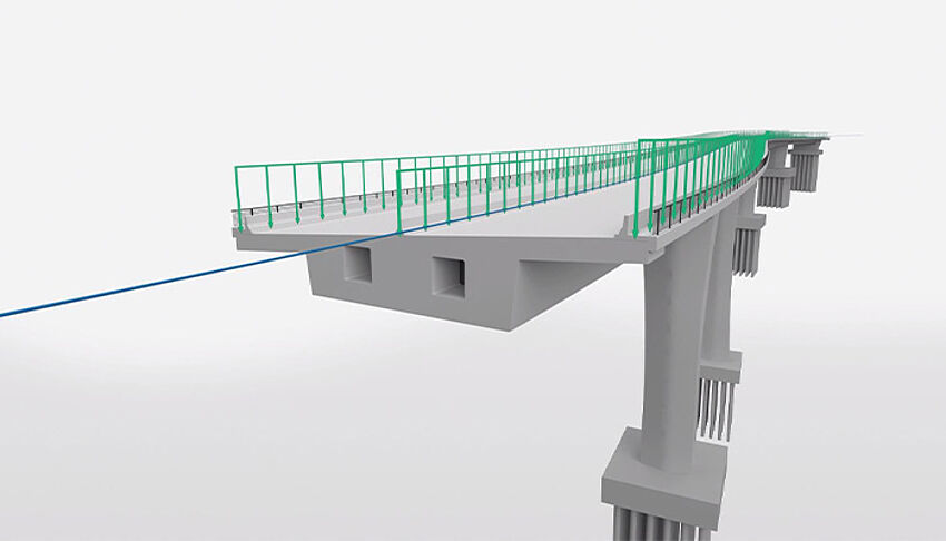
Visualization facilitates collaboration and communication between project stakeholders. All disciplines can analyze the model together for details, improvements, etc. Integrated CineRender from Maxon enables you to create high-quality visualizations intuitively and efficiently in any design phase – in the conceptual phase it is important tool for demonstrating all the variants and choosing the optimal solution, and in the detailed design phase it empowers stakeholders by minimizing design errors
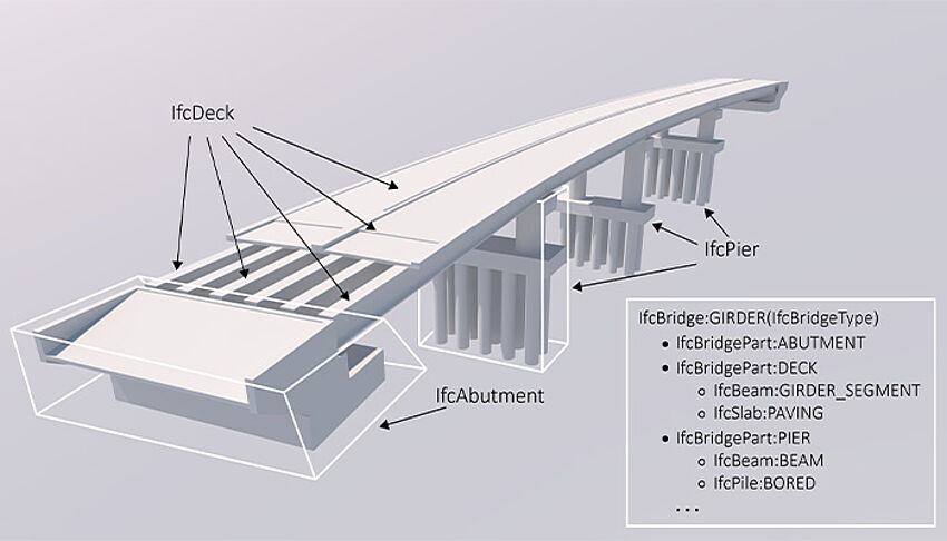
Attributes compliant to IFC 4.3 can be added in Allplan Bridge. IFC object definition can be assigned for objects directly while creating the cross-section. A hierarchical tree of spatial elements can be defined by utilizing IfcFacilityPart and IfcFacilityPartType directly in Allplan Bridge. Further arrangement of the spatial elements can be accomplished in Allplan, after transferring the model. Naturally, custom defined attributes can also be added in Allplan.
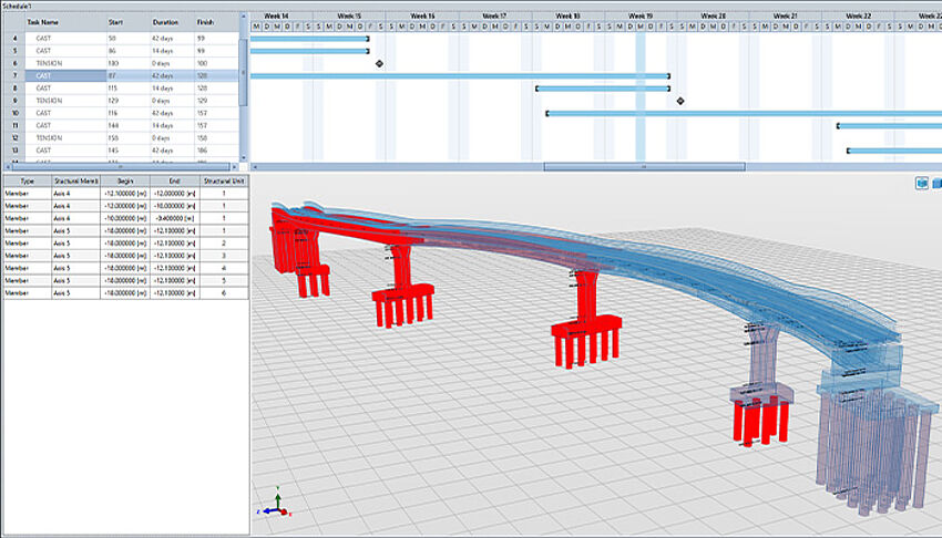
Time as the 4th dimension is considered when specifying the construction process. The construction plan is divided into several phases and further into individual tasks, such as concrete hardening, tendon stressing, activation of self-weight etc. The related structural components are interactively assigned to these tasks and this assignment connects the time attributes to the structure.
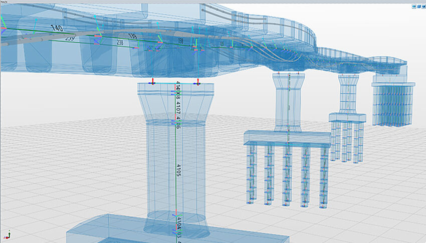
In Allplan Bridge the structural model does not need to be modeled from the beginning but the existing geometrical model is used as a basis. With some minor analysis relevant definitions, the geometrical model is complemented, and the analytical model can be generated automatically. This automated process is completely user controlled.
The product analyses the previously defined construction schedule and assembles all necessary calculation definitions in an automated process, like load cases, element activation and calculation actions. This includes also relevant data for calculating nonlinear time effects, creep, shrinkage and relaxation. The complete process is documented such that complete transparency is enabled.
The weight and the position of superimposed dead loads are automatically retrieved from the geometrical model. Further loads, like temperature change, wind loads, settlement, loads due to braking and acceleration, etc. can be defined and applied easily as well. The structural components that need to be loaded are interactively assigned to these tasks and this assignment applies the load on the beam elements.
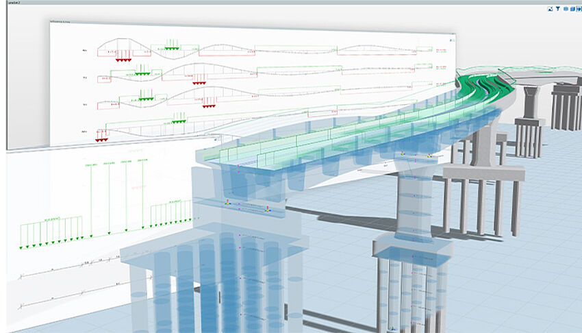
Traffic loads can be defined/applied in a very convenient way. On the one side, the traffic load is automatically applied in accordance with the selected standard. On the other side, the generic approach of live load definition implemented in Allplan Bridge allows the user to consider any type of moving load. The calculation allows for calculating the most unfavorable effects due to traffic and is based on the theory of (related) influence lines allowing an easy and swift calculation.
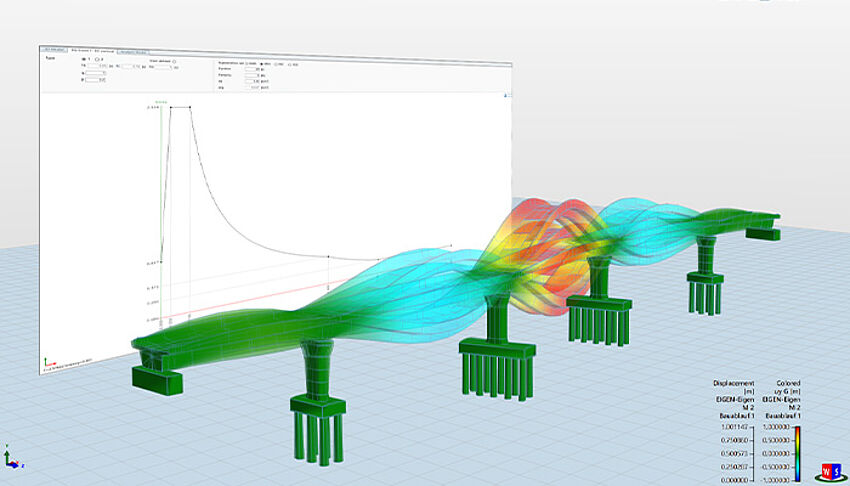
Allplan Bridge uses the multi-mode Response Spectrum Method for evaluating the effects of seismic loading. The solution consists of 2 separate tasks in the calculation procedure, firstly the determination of the relevant natural modes of the structural system and secondly the evaluation of the response spectrum prescribed in the design code.
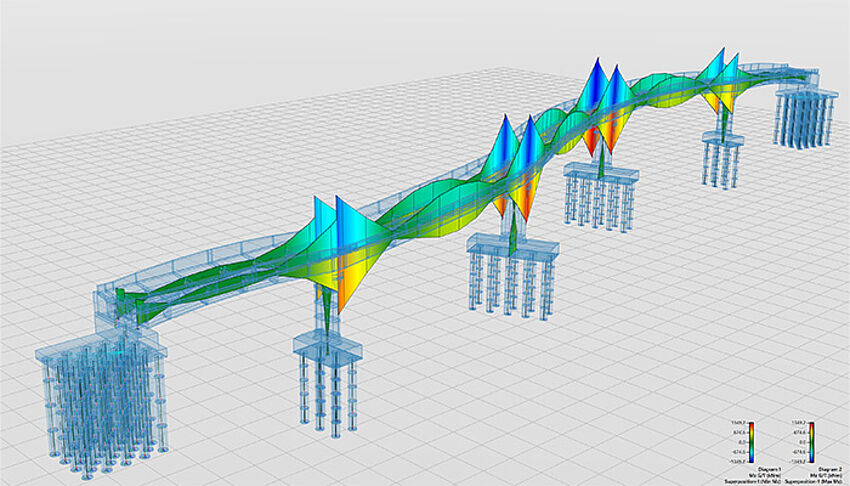
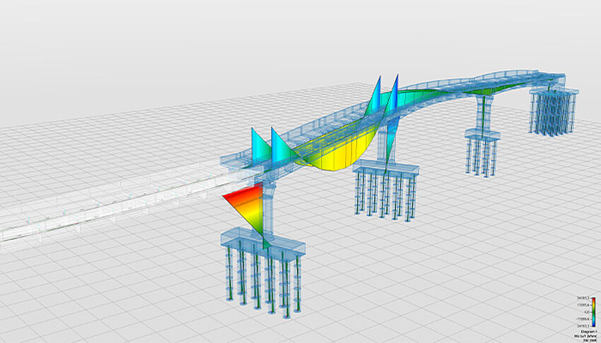
A global static analysis based on the Bernoulli beam theory is performed for all automatically and manually generated calculation actions defined previously in the construction sequence definition. The analysis is enhanced to accurately consider the cross-section variation. Furthermore, the nonlinear calculation of time dependent effects is performed, considering design code regulations.
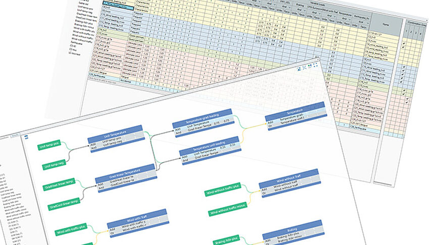
The user-friendliness and usability of the superposition in Allplan Bridge is groundbreaking. The schematic definition combines maximum flexibility and optimal overview. The same is true also for the definition of combinations. The table form gives the user an overview not only of the defined load factors but also of different types of combinations. The combination type becomes an important attribute when the code-based design is performed. This allows specific design procedures for automatically using the corresponding combinations.
Once the global effects are calculated and the relevant envelopes have been created the user can perform code dependent design tasks to determine the required reinforcement content. After the reinforcement area has been calculated or manually specified, ULS and SLS checks can be performed according to different international standards.
Parametric model description empowers the user to easily change and investigate different design solutions. The complete environment in Allplan Bridge is parametric – the geometrical and the analysis model and the construction sequence with all loads, combinations and design checks. Furthermore, it is possible to define different schedules for the same bridge structure. All this enables the user to analyze different design variants and, in this way, to optimize the bridge structure.
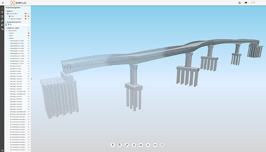
After the variant study and the structural analysis, model changes are part of everyday planning. Thanks to Bimplus, these changes can be easily documented, which facilitates the smooth construction process of the bridge project.
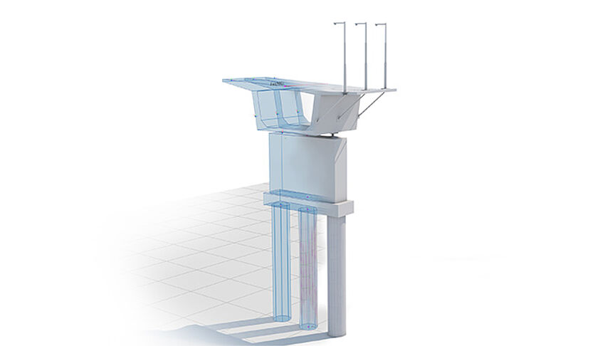
Parametric objects from the Allplan library, can be referenced in Allplan Bridge to add further details such as reinforcement, anchor devices of tendons or lamp posts to the bridge model. To do this, reference points are defined and linked to the object in the Allplan library using the respective name. When the parametric model is transferred to Allplan, the corresponding objects are positioned and adjusted whenever the model is updated.
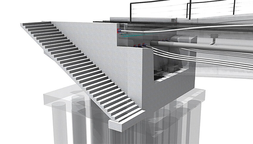
Powerful 3D modeling functionality allows the user to implement all bridge details without compromise: simply, flexible, and with the highest level of precision. The Parasolid® modeling kernel from Siemens handles intricate free-form geometry based on B-Splines and NURBS as well as standard tasks such as joints, cut-outs and drainage with ease.
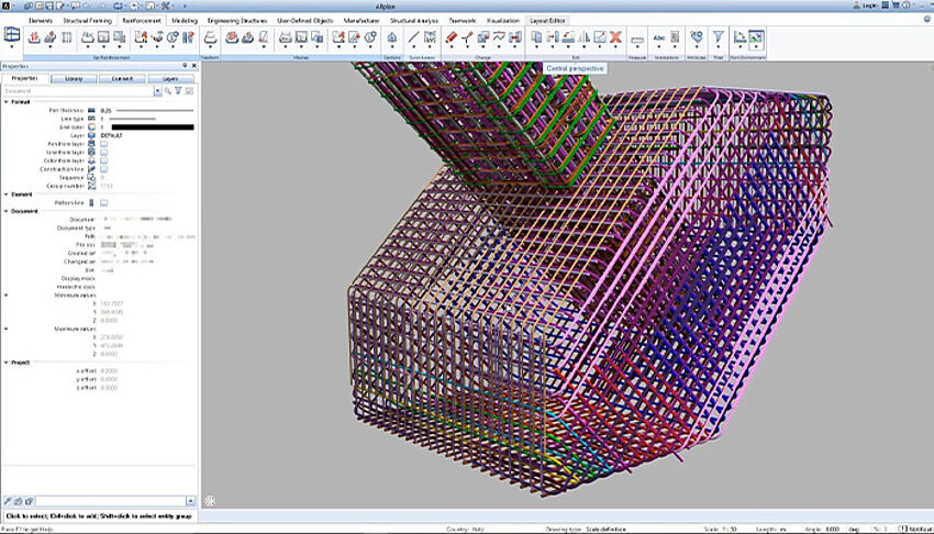
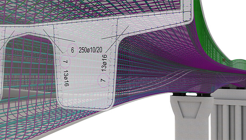
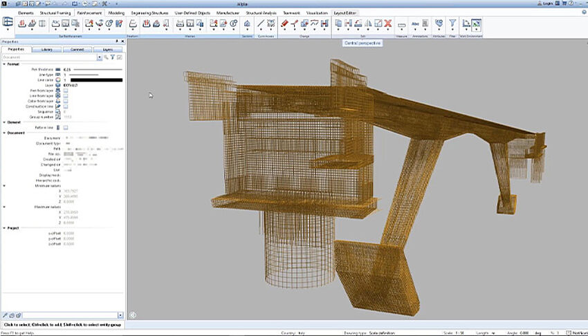
With Allplan, even challenging bridges with double curvature and varying cross-sections are reinforced conveniently and rapidly. The reinforcement is defined in different cross-sections and the transitions between the cross-sections are described with paths. Various rules can be defined, such as how the reinforcement joints are to be carried out. Using this information, the reinforcement is automatically generated.
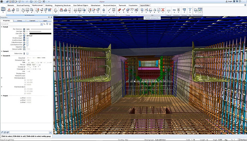
Thanks to 3D reinforcement in Allplan, errors in the design process can be minimized. With just a few clicks, you can check your model for collisions and then create steel lists. In this way, Allplan enables precise reinforcement drawings in the shortest possible time
Visualization facilitates collaboration and communication between project stakeholders. All disciplines can analyze the model together for details and improvements, etc. The visual representation of the bridge facilitates feedback. Thanks to the excellent visualization quality, structural features such as the level of detail of the reinforcement can be checked in real time and discrepancies can be resolved quickly.

Öngerilme de dahil olmak üzere yüksek düzeyde ayrıntıya sahip parametrik model oluşturmadan, inşaat sürecinin entegrasyonuna ve köprü modelinin yapısal analizine kadar tek bir çözümle çalışın.

3B parametrik model açıklaması, yol paftasını, köprü hizalamasını ve gerekli kesitleri dikkate alarak model yapılandırmasını ve varyasyonunu hızlı ve kolay hale getirir. Bu, doğrudan yazılımda veya hatta kodlama yoluyla yapılabilir.

Allplan Bridge, geometrik modelden analiz modelini otomatik olarak oluşturur. Bu, çalışma miktarını ve hatalara duyarlılığı büyük ölçüde azaltır.

Tüm kalıcı ve değişken yükler, son bir zarf içinde birbirleri arasında birleştirilir. Bu zarf, donatı tasarımı ve kod kontrolü yapmak için kullanılır.

4B modelin tamamı, hizalama ile ilgili olarak herhangi bir değişiklik olması durumunda ayarlanır. Bu nedenle, bir eksenin geometrisi değişirse, tüm köprü modeli otomatik olarak ayarlanır.

Doğrudan 3B modelden hızlı ve doğru bir şekilde planlar, çizimler ve raporlar oluşturun ve yüksek kaliteli belgeler için bilgi alışverişini kontrol edin.